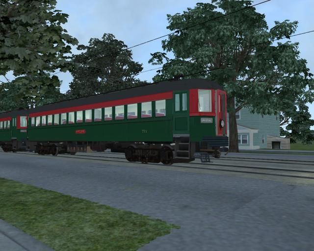
These were high speed cars, capable of about 80mph. The physics currently applied to them are a mesh of the Southern Railway 2BIL's (another of Richard's models). I am working on a set of physics to better suit the real thing. I am currently trying to set up the tractive effort vs. speed and tractive effort vs throttle to reflect their performance. You see, the cars control is set up somewhat unusual to the typical Trainsim Multiple Unit. They featured manual acceleration. The controller consisted of 11 points which were advanced through to accelerate the car.
Points 1-4 were Series points with a certain amount of resistance which decreased as you advanced up the controller. This allowed the motors to accelerate smoothly and not be exposed to 600V DC from a dead stop. 1 was enough voltage to barely get the car rolling, 2 a little bit more, 3 really started the car moving, 4 was a bit more from that, and finally, the 5th point was the car running in full series (no resistance). The 6th point was full series with a field tap, which shortened the electrical field in the motors a litle bit more. 5 and 6 are known as running points, which you hold indefinitely, keeping the car moving. Top speed here was 40 to 45 mph. Points 7-11 moved the car into parallel, (technically the two trucks under the car parallel with each other). As in parallel, points 7-9 were resistance points which allowed the car to accelerate up from the full series speed to full parallel speed. Points 10 and 11 mimicked point 5 and 6, only in parallel. Top speed here was about 80 mph. (82.5 the purported record in the most ideal conditions).
I notice that there are two simulation curves governing the behavior of the car when under power, tractive effort vs throttle and tractive effort vs speed. Can someone explain the relationship here? Are the values within for Tractive Effort a percentage of the max value in the simulation blueprint, or are they actual values? Furthermore, which takes preference in the performance of the car? I can see limiting the tractive effort in the throttle graph to allow the car to balance in point 6 at 45mph, but then boost it back up in further points to allow the car to reach 80mph in the 11th point. But, I don't know what effect the tractive effort vs speed graph has on that. While on the subject, is it possible to calculate a tractive effort when it is unknown? I have the total horsepower produced by the car (560hp) and the weight (103,800lb). From that can I come up with a tractive effort?
Another issue which needs to be overcome is the brakes. I have placed certain known values where I *think* they go. (according to the Railsim Developers Docs). The cars run on "Automatic Air" I am told, sort of a variation on a locomotive triple valve system. The brake pipe runs at 70psi released, and the main reservoir is charged at 100 psi. Usually a full application is 20lbs below brake pipe (beyond that the system is equalized and further reductions are ineffective). I have the car set up with the appropriate brake stand (release-hold-apply-emergency). However, when taking a braking reduction, the brake cylinder will continue to build beyond 20 psi, even though the brake portion of the simulation file tells it that the max is 20. Is there some value which needs to be tweaked to stop it from applying further?
Thanks,
Zach
